Difference between revisions of "3D Scanner"
From __space Wiki
| Line 27: | Line 27: | ||
*Go to the '''Scanners''' tab, our scanner should be read as HDI 120. | *Go to the '''Scanners''' tab, our scanner should be read as HDI 120. | ||
| − | * | + | *Click on the '''Auto-Configure''' button to configure the LAN connection between the PC and the scanner (requires administrator password). |
| − | * | + | *The connection is now ready and the scanner should show some data on the right hand side of the screen. |
*From the “BASIC” tab, select “Waypoint”. (This generates the new items “Move…” and “Waypoint” in the list on the left) | *From the “BASIC” tab, select “Waypoint”. (This generates the new items “Move…” and “Waypoint” in the list on the left) | ||
Revision as of 11:26, 27 February 2018
LMI Technologies HDI 100 3D scanner : Assembling units
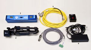
Please see the image to get the list of items.
- Attach the HDI 100 scanner (1) to the table-top tripod (2) head by hand-tightening the head knob.
- Connect the Power and Ethernet Cordset (3) to the Power/LAN connector (4) on the scanner. Then, hand-tighten the cordset.
- Connect the Power barrel jack of the Power and Ethernet Cordset to the Power Supply.
- Connect the Ethernet RJ45 plug of the Power and Ethernet Cordset directly to the computer.
Now, the scanner is all set. Lets set up the Rotary Table (5):
- Connect the RJ11 plug of the USB to RJ11 cable (6) to the rotary controller.
- Connect the Power Supply Adapter Cable (7) to the power supply.
- Connect the USB connector of the USB to RJ11 cable to the computer.
Now, you can plug the power cords of both the scanner and the rotary table to the power supply.
Configuring the 3D scanner software
- Make sure the scanner is ON, connect the USB license key to the computer then open the FlexScan3D software.
- Go to the Scanners tab, our scanner should be read as HDI 120.
- Click on the Auto-Configure button to configure the LAN connection between the PC and the scanner (requires administrator password).
- The connection is now ready and the scanner should show some data on the right hand side of the screen.
- From the “BASIC” tab, select “Waypoint”. (This generates the new items “Move…” and “Waypoint” in the list on the left)
- Select “Waypoint” from the list, then go to the Command tab.
- Select “Set this waypoint”
- You will be taken to a new screen with various movement controls. It is recommended to either use the arrows to move each joint individually (lower right portion of the screen), or alternatively you can press and hold the button labelled: “Freedrive”, which allows you to drag the robot arm to the desired location by hand.
- Once you have placed the arm in the desired location, select “OK” in the bottom right corner of the screen.
- The first waypoint is now set and you can repeat the steps above to program the next movement.
Helpful Tips
- When programming the first waypoint, it is helpful to start with a “stowed” position which the robot arm can start from. If you are programming a lot of actions it becomes increasingly beneficial to return the arm to this position to iron out errors as you go along. You can also repeat this waypoint in the final step of the program so the arm can return to the initial position; this makes for a more seamless loop when the program repeats.
- When programming finite movements, think “connect the dots”; a straight line will require only two waypoints, while a curve will require multiple waypoints placed closer together.
- It is best to verify and troubleshoot each set of movements as they are completed. If you wait until you have a whole string of movements before checking the program you may run into complications which will be much more difficult to fix.
    o To troubleshoot, you can select any movement you have already programmed, then select “move robot here” from the command
      screen.
    o Doing this in series with about 3-5 waypoints at a time helps to keep all movements on the desired track.
- Select “Set this waypoint”
- You will be taken to a new screen with various movement controls. It is recommended to either use the arrows to move each joint individually (lower right portion of the screen), or alternatively you can press and hold the button labelled: “Freedrive”, which allows you to drag the robot arm to the desired location by hand.
- Once you have placed the arm in the desired location, select “OK” in the bottom right corner of the screen.
- The first waypoint is now set and you can repeat the steps above to program the next movement.
